These days Enterprises are going ahead with their plans for clustering as a mandatory factor in their mission-critical applications. There are many articles scattered over the internet on J2EE clustering using several application servers. There is a nice article on J2EE Clustering that gives an overview on the fundamentals of clustering and its implementation. But being unable to locate such an article that describes a step by step instruction and pitfalls for a particular condition like mine, I studied many of them and sorted out a specific roadmap as demonstrated in this article. It might help someone facing a similar situation.
As per my understanding, a cluster is a logical group of application servers that hosts applications transparently like a single entity and provides a continuous availability to the application. It also provides a high scalability of the application based on the increasing user access.
Clustering in McDonald’s
Envision a situation where there are four counters in a McDonald shop. Three customers are getting dished up at three counters. Once another customer enters the fourth counter is ready for serving. This could be a simple example of scalability. We observe a similar scenario in clusters. When all member servers in a cluster are loaded with multiple requests and a new request comes in, the cluster tries to find out a member server that is less busy and routes the request to that. It’s known as load balancing. There are multiple methods used in load balancing e.g. Round Robin, Server Affinity and Weight based etc. Load balancing is accomplished differently for different application resources. For example, the load balancing mechanisms for Servlets/JSPs could be different from EJB.
Supposing a sales-person operating one of the counters gets occupied by some urgency while serving a customer, he/she can hand-over the customer’s request to another sales-person. This could be an instance of Session Replication and failover. In clusters we see that if a severe problem drives one of the member servers to crumple, another member server immediately takes over the requests that were being served by the previous one and starts acting on them in order to keep the client transparent from the failure. By this feature the applications can be made more highly available to the users. Persistence of a session is necessary to replicate the session. Application server vendors use multiple mechanisms to implement Session Persistence e.g. Memory based, Cookie based, File based, JDBC based and In-memory based etc.
Let us go little more inside the shop with the permission of the shop owner (just kidding). The requests were jotted down on a piece of paper (a good example of session persistence) and routed to the chef who cooks a yummy dish for you. Again there could be many chefs operating in that shop (another cluster). Based on who is less busy the request is being routed to him/her (load balancing again). We can clearly see that there are members working in two different layers (sales-person layer and chef layer) in that shop. Similarly we can have two layers in clustering as well – a layer web server cluster and a layer of application server cluster.
Experiment on MyWeb application
In this article I will describe a case study on clustering and try to sketch a blueprint based on my personal experiences.
I got assigned to a project that was requiring an R&D on J2EE clustering to provide scalability and high availability to a commercial web application. The size of the application is nearly about 25mb including static and dynamic contents (mainly Servlets, JSPs and Java beans) and was installed on a single instance of WebLogic server. The application was also using JDBC connection pools and data sources configured for Sybase database. A hardware load balancer was used to route requests to the WebLogic server. There was no failover implemented around the application.
In order to maintain the business secrecy imaginary names and values for the application, servers, machine IP addresses and other resources have been used in this article.
Going further “machines” are referred as the hardware boxes and “logic machines” as a concept used in WebLogic environment.
Goals and assumptions
The main goals behind the experiment was to
1. Implement clustering for the application – “MyWeb” using a web server layer (Apache Httpd) and an application server layer (WebLogic).
2. Deploy using the staged deployment scenario. In this scenario the member servers have their own individual copies of the application being deployed.
3. Replace the hardware load balancer to use web server proxy load balancer.
4. Use multiple machines running on different Operating Systems.
5. Implement the feature of Http session replication as a failover strategy using In-memory session persistence.
6. Separating out the static and dynamic contents at the web and application server layers. This enhances the performance of an application if you have considerable amount of static contents.
Clustering Roadmap
To be able to meet the goals I figured out a roadmap to move ahead. The steps involved are
# Getting the clustered version of WebLogic.
# Figuring out the clustering topology. A plan or blueprint of how the machines, servers, operating systems to be laid out and how the application will be deployed on them.
# Selecting the load balancing mechanism.
# Selecting the participating machines (hardware) for installation.
# Installation of same version of WebLogic on all boxes.
# Configuring WebLogic administration server and WebLogic domain.
# Configuring WebLogic logical machines (representing the physical machines in WebLogic environment or domain) and Node Managers for them.
# Configuring managed instances and assigning them to logical machines.
# Configuring WebLogic clusters and assigning the managed instances to the clusters.
# Installing Apache Httpd as a web server and installing WebLogic proxy plug-in on it and configuring the httpd.conf file to make it point to the WebLogic cluster. # Starting WebLogic Administration Server, starting node manager on every participating machine and registering them to the administration server.
# Starting the managed instances from the Admin Console.
# Configuring the application servers (admin and managed) with application (to be deployed) specific settings such as creating JDBC connection pools, setting the security policies to a customized one etc.
# Deploying an application e.g. MyWeb on all the member servers together.
# Configuring the servers with application specific settings, if any and starting the application.
Ingredients & recipe
To start with, here is a list of tools, software, machines, operating systems that was involved during this experiment. I arranged for a clustered version of WebLogic 9.2.1 both for Windows and Linux. In fact I banged on a road block for using WebLogic 9.2.1 for Linux and 9.2.0 for Windows. Unfortunately they are rigid enough to refuse the communication among the member servers with different versions. Apache Httpd 2.0.59 (no_ssl version) can be downloaded from the Apache website. Well there is another compatibility hick-up between WebLogic 9.2.1 and Apache Httpd latest versions with the proxy plug-in provided. So I had to pull back to Apache Httpd 2.0.59.
Since the plan was to use two layers (web layer and application layer) distributed on multiple machines in a heterogeneous environment, three machines were considered with the following configuration.
First machine with an IP address 1.1.1.1 running Redhat Linux 5.2.1 on it, referred as WL1 for the rest of this article.
Second machine with an IP address 1.1.1.2 running Windows2003 on it (referred as WL2).
Third machine with an IP address 1.1.1.3 running WindowsXP on it (referred as AP1).
While selecting a load balancer I had two options. One is to use the hardware load balancer and the other is using the application server proxy plug-in. Since the goal is to avoid the former one, the later was opted for. WebLogic provides a proxy plug-in for most of the popular web servers to be used between the web server and application server layers. It helps the web server to balance the load and route the requests to the appropriate WebLogic server in a cluster. This plug-in can be configured to support SSL as well, but I decided to avoid that for now.
As per my plan I sketched a topology as shown in figure 1 below.
 Figure 1
Installation of WebLogic on WL1
To proceed with the installation of WebLogic on WL1, I followed the steps as below.
· Created a directory as /opt/bea.
· Copied the platform921_linux32.bin to /opt/bea.
· Used “chmod a+x platform921_linux32.bin ./platform921_linux32.bin” to change it’s mode to execute.
· Used “./platform921_linux32.bin -mode=console -log=./platform_install.log” to install in console mode. For a detailed description on how to start WebLogic in console mode follow the instructions given at Starting the Installation Program.
· For a step by step instruction on how to continue with the installation program you can refer to the article Running the Installation Program in Console Mode.
· The BEA_HOME was made to point to /opt/bea.
· Installed only the “Server” and “Web Server Plug-Ins” from the list.
· Selected the server startup more as “Production Mode”, ignoring the installation of “Mercury profiling tools”. This is installed only for “Development Mode”.
· The product directory in my case was /opt/bea/weblogic92.
· Once the installation script was completed, to set the environment I executed “./setWLSEnv.sh” under /opt/bea/weblogic92/server/bin.
Installation of WebLogic on WL2
Now we need to switch over to WL2 machine (IP: 1.1.1.2 running Window 2003) to install WebLogic. For this I
· Copied the platform921_win32.exe on WL2.
· Created a directory c:\bea as the BEA_HOME.
· Started platform921_win32.exe.
· The rest of the steps are pretty much similar as followed for WL1 except the command line interface, rather you get a cool and nice GUI mode for installation on windows.
Once we are finished installing WebLogic on WL2, a windows service will be automatically installed and started for WebLogic Node Manager. Node Manager is a software agent employed by WebLogic to control server instances remotely.
Configuring WebLogic Admin and Domain
As the most vital part, we will configure the WebLogic Admin Server and domain on WL01. Here are the steps I followed.
· Moved in to /opt/bea/weblogic92/common/bin on WL1.
· Started “./config.sh –mode=console” to start the Configuration Wizard in console mode. You can refer to the article - using Configuration Wizard for details.
· Picked up “Create a new WebLogic domain” in the “Welcome” screen.
· Selected “Choose WebLogic Platform Components” in “Select Domain Source” screen.
· Entered WebLogic Admin Server username and password both as “weblogic”.
· In “Domain Mode Configuration” screen “Production Mode” is selected.
· In “Java SDK Selection” screen “Sun JDK 1.5.0_06” is selected.
· In “Choose Configuration Option” screen “Yes” is selected.
· Modified the Admin Server name as “MyAdmin”.
· Modified the IP address to 1.1.1.1. By default the IP address points to 127.0.0.1 and there is a problem with using an IP address of x.0.0.1 range as your multicast IP (refer to Using WebLogic Server Clusters). Finally the "Choose Configuration Option" screen looked like below.
Name Value
__________________________________
1 *Name: MyAdmin
2 Listen address: 1.1.1.1
3 Listen port: 7001
4 SSL listen port: N/A
5 SSL enabled: false
I skipped all steps to reach the “Edit Domain Information” screen and entered the domain name as MyDomain. Once the config.sh script gets completed on WL1 we can see the domain is created under /opt/bea/user_projects/domains/MyDomain unless you have specified a different path for the domain directory during the configuration.
So far WebLogic is installed on WL1 and WL2. The Administration Server is configured on WL1. Since I am slow at typing, carrying out the rest of the process with the Admin Console GUI was an easy option for me. Just a few steps before that to start the Admin Server
· Added ReverseDnsEnabled=true in /opt/bea/weblogic92/common/nodemanager/nodemanager.properties. Same change was made on WL2 as well. This helps the Node Manager to lookup hostnames through DNS entries both on 1.1.1.1 and 1.1.1.2.
· Moved over to /opt/bea/weblogic92/server/bin and started the Node Manager as a background process by “./startNodeManager.sh &”.
· Moved in to /opt/bea/user_projects/domains/MyDomain. Added the lines below in startWebLogic.sh to avoid the username and password prompt and then save the file.
WLS_USER=”weblogic”
export WLS_USER
WLS_PW=”weblogic”
export WLS_PW
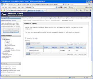
Figure 2
Starting Admin Server on WL1
· Start the Admin Server by “./startWebLogic.sh”. This will start the Admin Server.
· After the server has been started you can open the Admin console GUI on your browser at http://1.1.1.1:7001/console and log in using the username and password that you have specified during the Admin Server configuration. I used “weblogic” as username and password both.
· Once the Admin Console opens up, select the MyDomain -> Environment -> Servers to see if the Admin Server is running with good health as shown below in figure 2.
Creating WebLogic Cluster
· To create a cluster, follow the MyDomain -> Environment -> Clusters link. Click the “Lock & Edit” button on the top left corner to be able to edit the configuration page.On the right pane, click on the “New” button and specify the cluster details in the page as shown in figure 3. A WebLogic domain can be constituted of multiple clusters. Well I need just one for now.
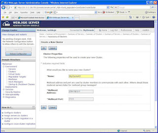
Figure 3
The multicast address is set as 239.192.0.0 and the port is set as 7001 by default. I altered them to ensure that there is no conflict with another processes already running on the same machine and port. You can set the address to any IP between 224.0.0.0 and 239.255.255.255 (refer to Using WebLogic Server Clusters).
WebLogic Server uses IP multicast communication among the servers in a cluster mainly for two purposes.
1. To send and receive Cluster-wide JNDI updates. Since WebLogic uses a Shared Global JNDI implementation, the servers keep on monitoring the availability of the objects in the local JNDI tree and update other members of the cluster about it. Similarly they receive messages from other members and update their own JNDI tree accordingly.
2. To send and receive Heartbeat messages. This communication helps a member server in a cluster to determine whether another member has failed.
Click on the “Activate Changes” button at the top left corner to send a request to the Admin Server to actually create the cluster (figure 4). The cluster does not have any servers in it till now. We will add servers to it in the following steps.
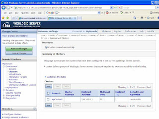
Figure 4
Creating WebLogic Machines
In the following step you need to create and configure WebLogic Machines through the "Configure Machines" screen. A WebLogic Machine is a logical representation of the physical machine (computer) that hosts one or more WebLogic Server instances. This is specially required when the cluster spans across different physical machines. There are two main purposes to have WebLogic Machines.
1. To ensure that server session data is replicated on separate pieces of hardware.
2. To ensure the Node Manager is able to have control on the remote servers.
If a Node Manager runs on a machine that does not host an Administration Server, as in the case of my WL2 machine, so I created two machine configurations for WL1 and WL2.
· Follow the link MyDomain -> Environment -> Machines and click on “Lock & Edit” button.
· Click “New’ button on right and enter the machine name as “MyMachine01’ in the following screen.
· Select the “Machine OS” as “other” and click “OK”.
· Click on “Activate Changes” button on the next page at the top left corner.Once the machine is created as MyMachine01, follow the link on “MyMachine01” and then to “Configuration -> Node Manager” tab to arrive at the page as shown in figure 5.
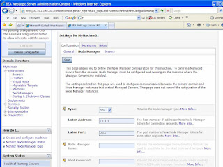
Figure 5
- The “Listen Address” was changed to 1.1.1.1 and followed by a click on the “Save” button.
- You need to click to “Activate Changes” button at this point.
- This will modify the Node Manager address when it’s I restarted next time.
- Similarly two WebLogic machines were created as described below.
  Name*       Node manager listen address Node manager listen port
__________________________________________________________________
1 MyMachine01                     1.1.1.1                     5556
2 MyMachine02                     1.1.1.2                     5556
Creating Managed Servers
- Next part is to key in the details for the managed servers.
- Follow the link MyDomain -> Environment -> Servers and click on the “Lock & Edit” button again.
- Click on “New” button on the top of the servers table on the right.
- Enter the details as shown in figure 6 to create a managed server called “MyManaged01” in MyCluster01 and click “Next” button. Click “Finish” button in the following screen.
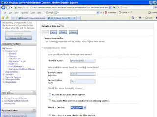
Figure 6
- Once the managed server is created as MyManaged01 in the server table, I followed the link on “MyManaged01’ to go to the Configuration -> General tab in “Settings for MyManaged01” page and clicked on “Lock & Edit” button.
- You need to modify the “machine” to “MyMachine01” here to assign this server to MyMachine01. Figure 7 shows the configuration change.
- To apply the change we need to click on “Save” button and then on the “Activate Changes” button.

Figure 7
Similarly four managed servers were created as described in the table below.
    Name*         Listen address  Listen port  SSL listen port  SSL enabled
___________________________________________________________________________
  1 MyManaged01   1.1.1.1         7101               N/A        false
  2 MyManaged02   1.1.1.1         7201               N/A        false
  3 MyManaged03   1.1.1.2         7301               N/A        false
  4 MyManaged04   1.1.1.2         7401               N/A        false
Notice that, I have created MyAdmin as the WebLogic Admin Server listening on port 7001, two managed servers as MyManaged01 and MyManaged02 listening on ports 7101 and 7201 respectively on WL1 machine (IP: 1.1.1.1). We need to ensure that the combination of IP and port should be unique for all the server processes. Rest of the two managed servers MyManaged03 and MyManaged04 were created on machine WL2 (IP: 1.1.1.2) and made to listen on ports 7301 and 7401 respectively. When all managed servers were created, the server table appeared as shown in figure 8.

Figure 8
Configuring Node Manager on WL2 using WLST
As per my strategy, the Administration Server is going to be on WL1 and WL2 machine will run a Node Manager to communicate with the Administration Server for controlling the cluster. To accomplish this, the Node Manager on WL2 has to be registered with the Admin Server hosted on WL1. I did it with the aid of WebLogic scripting tool (WLST). The WebLogic Scripting Tool (WLST) is a command-line scripting interface that system administrators and operators use to monitor and manage WebLogic Server instances and domains. The WLST scripting environment is based on the Java scripting interpreter, Jython. The steps are given below.
Log in to WL2 machine.
Open a command window and move in to C:\bea\weblogic92\common\bin\ directory.
Start wlst.cmd. It takes you to a prompt like wlst:/offline>
Issue the command below at the prompt. It connects WLST to the Admin Server running on WL1.
wlst:/offline>connect('weblogic', “weblogic', 't3://1.1.1.1:7001')
The prompt immediately changes to wls:/MyDomain/serverConfig> if the connection is successful.
To register "MyDomain" with the node manager running onWL2 use
nmEnroll("c:\\bea\\user_projects\\domains\\MyDomain"). Directories will be created by node manager automatically after doing this.
Come out of WLST with wls:/MyDomain/serverConfig>exit().
Restart the Node manager (Control Panel -> Admin. Tools->Services) on WL2.
 Figure 9
Starting the Cluster
Finally we can now start our cluster from the Admin Console (http://1.1.1.1:7001/console).
Go to the MyDomain and on the right pane go to the “Control” tab.
Check the boxes for all four managed servers and hit “Start” button as depicted in figure 9.
I came across an error while starting my servers as
<BEA-090482> <BAD_CERTIFICATE alert was received from 1.1.1.1
I found out a remedy to avoid this error but still looking for a permanent workaround. To fix this, click on the “Lock & Edit’” button to start editing the configuration. Go to MyDomain -> Environment -> Servers -> MyAdmin -> Configuration -> SSL -> Advanced and turn the “Hostname Verification” to “None”. Save the changes by clicking the “Save” and then the “Activate Changes” buttons. You should restart the Admin Server at this stage to apply the changes. Once the servers are started the server table will look like as shown in figure 10.
 Figure 10
Keep refreshing this page and it will finally come up with a status as shown in figure 11 indicating that your WebLogic platform is up and running with a multihomed (with multiple machines) clustered topology.
 Figure 11
Deploying and starting MyWeb application on WebLogic cluster
Our following step will be to deploy the “MyWeb” application on “MyCluster01”.
- Before starting the deployment a useful step is to enable the Clustered Constraints. It enables the two phase deployment in a clustered environment. This feature enables applications to be deployed successfully on all the member servers at the same time. If one server fails the entire process is stopped. You can go to MyDomain -> Configuration -> General tab and turn on the “Enable Clustered Constraints“.
- I created some JDBC data sources since MyWeb needs a couple of them. You can create JDBC data sources under MyDomain -> Services -> JDBC -> Data Sources.
MyWeb application was packed in a WAR file. Before packing you application ensure that the WEB-INF directory should have a weblogic.xml containing the lines below.
<session-descriptor>
<session-param>
<param-name>PersistentStoreType</param-name>
<param-value>replicated</param-value>
</session-param>
</session-descriptor>
The above lines ensure the replication of Http session for an application.
 Figure 12
- In the next page select “Install this deployment as an application” and click “Next”.
- The following page will ask for a target for the deployment where you need to select MyCluster01. With this option the application will be deployed on all the servers belonging to MyCluster01. Click “Next” here.The following page will appear as shown in figure 12. I accepted the default option shown in this page and clicked next. The default source accessibility option i.e. “Use the defaults defined by the deployment's targets” means the deployment will be done in a staged mode for all the managed servers and non-staged mode for the Admin server (not applicable in my case since I am not deploying MyWeb on the Admin server). In a staged deployment the source WAR file will be downloaded or copied by all the servers to have their own copies, while the non-staged option shares the source from a single location. Staged mode is specially suggested when you have a multihomed WebLogic domain. It avoids the single point of failure. Supposing in a non-staged mode, when the server hosting the application source goes down the source will be unavailable to other servers in the cluster. I clicked the “Finish” at this page. The next page appeared as shown in figure 13.
 Figure 13
- The status of MyWeb application will appear as “distribute Initializing” Click “Activate Changes” button here. The status will change to “Prepared” immediately.
- The final step is to start the application. Click on the check box on the left of MyWeb and then on the “Start” button drop down. Select “Servicing all requests” option from the “Start” button drop down.
- Click the “Yes” button on the following page and Deployment table will appear as in figure 14 indicating that MyWeb application has been started successfully.
 Figure 14
With this you can conclude the WebLogic configuration chapter. Well that’s not all.
Installing and configuring Apache Httpd on AP1
I still need to setup my web server layer on the machine AP1 (IP: 1.1.1.3).
- To proceed with that start apache_2.0.59-win32-x86-no_ssl.msi to install Apache Httpd 2.0.59 on AP1 under C:\Dev\apache\httpd\Apache2.
- Once Apache Httpd is installed the Apache Service Monitor will be started.
- Since one of the goals of my R&D was to separate out the static and dynamic contents among web and application server layers, I created a directory as C:\Dev\apache\httpd\Apache2\htdocs\MyWeb on AP1 and placed the static contents of MyWeb application e.g. HTMLs, Java-scripts, images and style-sheets under this folder. Notice that you should create the directory with same name as specified for the application context in WebLogic (shown in the deployment table in figure 13).
Adding WebLogic Proxy Plug-in on Apache
- To install the WebLogic proxy plug-in for Apache Httpd, I copied the mod_wl_20.so file from /opt/bea/weblogic92/server/plugin/win/32/ on WL1 to C:\Dev\apache\httpd\Apache2\modules\ on AP1. mod_wl_20.so is the proxy plug-in provided by WebLogic for Apache Httpd 2.0.59.
- More information on Installing and Configuring the Apache HTTP Server Plug-In can be found on WebLogic website.
- To configure the proxy plug-in it’s mandatory that the mod_so.c module is enabled. I went to C:\Dev\apache\httpd\Apache2\bin and executed apache –l to verify that. It shows a list of modules installed with Apache.To make Apache point to the WebLogic cluster using the proxy plug-in, add the lines below in the C:\Dev\apache\httpd\Apache2\conf\httpd.conf file. The lines instruct Apache to route all requests demanding for dynamic contents to WebLogic. Since MyWeb was using Struts I added *.do extension as a parameter to MatchExpression option. The wlproxy.log is configured to record the activities during the routing. Logging and debugging parameters are optional.
LoadModule weblogic_module modules/mod_wl_20.so
<IfModule mod_weblogic.c>
WebLogicCluster 1.1.1.1:7101, 1.1.1.1:7201, 1.1.1.2:7301, 1.1.1.2:7401 MatchExpression *.jsp
MatchExpression *.do
Debug ON
WLLogFile c:/dev/apache/httpd/apache2/logs/wlproxy.log
DebugConfigInfo On
</IfModule>
- To route all request irrespective of static or dynamic content you can add the following lines.
<Location /MyWeb >SetHandler weblogic-handler</Location>
This will route all requests containing /MyWeb to the WebLogic cluster.
Testing failover and session replication with MyWeb
In my case the welcome file was MyHtml.html, so I brought up MyWeb at http://1.1.1.3/MyWeb/MyHtml.html. If you have an index.html to start with you can simply type http://1.1.1.3/MyWeb as the URL. MyWeb appeared as shown in figure 15 on my browser. See how it works with you.
You can check the c:/dev/apache/httpd/apache2/logs/wlproxy.log file to find out the name of the WebLogic managed instance to which the request is actually getting routed. From the log I discovered that MyManaged01 on WL1 was receiving the requests.
I checked the /opt/bea/user_projects/domains/MyDomain/servers/MyManaged01/logs/access.log to confirm that it’s really receiving the requests.
- I started a session with MyWeb and played around a little bit with it.
- Tried shutting down MyManaged01 forcibly from the WebLogic Admin Console (MyDomain -> Control tab) and found that the session got replicated to MyManaged02 on WL1. I further tried getting MyManaged02 down and found the session to be replicated to MyManaged03 on WL2.
 Figure 15
Notes
Socket Exception
There are couple of points that I would like to mention here. Since MyWeb had a large size of nearly 250mb I faced an error during the staged deployment as mentioned below.
<DeploymentService> <BEA-290065> <Deployment service servlet encountered an Exception while handling the deployment datatransfer message for request id "1,190,838,152,600" from server "MyManaged03". Exception is: "java.net.SocketException: Socket closed.
……
……..
java.io.IOException: Reached EOF
……
……..
java.lang.IllegalStateException: Response already committed <Error> <HTTP> <BEA-101083> <Connection failure.
……
……..
java.net.SocketException: Error in poll for fd=52, revents=32
……
……..
<Deployer> <BEA-149078> <Stack trace for message 149004
weblogic.management.DeploymentException: Exception occured while downloading files
……
……..
After having a tough time while searching for an actual reason for the errors, I found that during the staged deployment WebLogic uses an Http Servlet to download the application source to each of the managed servers in the cluster. The servlet was getting timed out and closing connections to other members in the cluster. As a remedy I followed the steps below.
Set the CompleteMessageTimeout in MyDomain -> Environment -> Servers--><server>-->protocol-->general tab from 60 seconds to 480 seconds for both the admin and all managed servers. Where “<server>” indicates the name of the server.
Set the IdleConnectionTimeout to 480 seconds for the admin and managed servers.
Went to Mydomain -> Environment -> Servers--><server>-->protocol-->HTTP and change PostTimeout to 120 (default:30 secs).
Try the same if you come across a similar problem.
Replication groups
During this experiment I tried building replication groups. A replication group is a preferred list of clustered servers to be used for storing session state replicas. WebLogic uses them to support failover in a cluster. WebLogic Server attempts to create session state replicas on a different machine than the one that hosts the primary session state. You can further control where secondary states are placed using replication groups.
In my case I created two replication groups as RepGroup13 and RepGroup24. RepGroup13 consisted of MyManaged01 and MyManaged03, while MyManaged02 and MyManaged04 were members of RepGroup24 as shown in figure 16. RepGroup13 was made to be the preferred secondary replication group for the members of RepGroup24; similarly RepGroup24 was designated as the preferred secondary group for the members of RepGroup13.
Considering all managed servers are up and running, once MyManaged01 receives a request and starts a session with a client, the session will be replicated preferably on MyManaged04 as a secondary server (based on the server ranking policy) rather than randomizing on any other member. Incase MyManaged01 goes down MyManaged04 will continue to serve the client with the session state collected from the point where MyManaged01 has collapsed. If replication groups are not configured WebLogic will pick up any member in the cluster as the secondary target based on a round-robin policy.
 Figure 16
I followed the steps below to create replication groups.
Opened Admin Console follow MyDomain -> Environment -> Servers -> MyManaged01 -> Configuration -> Cluster.
Entered RepGroup13 as the Replication Group for MyManaged01.
Entered RepGroup24 as the Preferred Secondary Group for MyManaged01 as shown in figure 17.
Saved Configuration by “Save” and “Activate Changes” buttons.
Similarly set RepGroup13 as the Replication Group and RepGroup24 as the Secondary Replication Group for MyManaged03.
Set RepGroup24 as the Replication Group and set RepGroup13 as the Preferred Secondary Group for MyManage02 and MyManage04.
Restarted WebLogic server.
 Figure 17
My next plan is to try a similar R&D on WebSphere and Apache Httpd unless I get caught with something more urgent, till then keep clustering ;)


