Tuesday, August 31, 2010
MBT
Another trend is catching up along with WEB2.0, SOA and EA (Enterprise Architecture) which is Business transformation or IT transformation to be specific. I believe this is going to be the next big thing in IT industry. Most of the enterprises who piled up multiple big and small applications to support their daily business transactions are realizing a need to consolidate the pool of software applications to have a better control monitoring and governance. There is a burning need to control the growth of IT landscape. As a result the enterprises are going for transformation of their IT stack. I foIn search for a standard methodology of business transformation found most of the consulting farms have come up with proprietary methodologies. There is one called MBT (Methodology for Business Transformation - http://www.doi.gov/archive/ocio/architecture/mbt/guidance.htm) presented by the US Department of the Interior. This is in fact in line with some methodologies that I have been using for the last couple of months. This method considers the vital ingredients of EA and IT governance along with the technical aspect of process re-engineering and transformation roadmap. As TOGAF describes the ADM (Architecture Development Method), MBT plays an important role in listing out the important activities to be done on the way to transformation.
Monday, July 26, 2010
BAM: Now and Beyond
BAM is still not matured enough to be used smoothly in an enterprise. It requires the implementer to take more responsibilities to fit with the business in context. But the promises that BAM brings in is really very beneficial to all the industries and businesses. If implemented in a proper way that fits with the business strategies it can bridge the gap between the business and the technology. The enterprises those roll out BAM will have an obvious advantage over their competitors with respect to the performance of the business systems.
As far as the agility is concerned, the best option for an enterprise to get the maximum benefit out of a BAM solution is to have centralized control over the business processes using a BPM platform and complement the same by a BAM framework. BPM will help the enterprise to have an end-to-end view on the business processes and their control while BAM will bring in the capabilities to monitor the changes, foresee a variation from the normal trend and act accordingly.
The changes that can be monitored by a BAM could be anything that happens in the market but the real intelligence that can earn a greater profitability for a business. This can be done with a continuous mining of news feeds and analyzing them to find out which are relevant to the business and can potentially change the landscape of a business. This is how technology can be employed to watch for the business opportunities like a hawk and enrich the business to proceed toward a profitable growth, operational efficiency, reducing operational costs and adaptability. CEP is a brainier and improved BAM that tracks the real time business events and figure out a business pattern based on the same. In case of a deviation from the normal pattern the CEP notifies and enables systems to resolve issues automatically.
Tuesday, June 29, 2010
Way to effective SOA Governance: A case study
There are multiple issues faced by conventional IT companies on the way to implement effective SOA governance.
As an example, we can consider a fictitious telecom service provider company as SDFTELECOM. They have various departments looking after customer management, inventory management, billing, service provisioning and activation. Each department has their own stack of systems to serve their respective areas of operation. Let us consider a set of systems participate in an end-to-end order fulfillment process. The systems were moderately integrated using SOA infrastructure. As per the ownership model followed, the participating systems belong to different departments of SDFTELECOM. With significant growth in business and increasing customer demand the systems need to undergo changes quite often. But due to the individual ownership of systems they are facing challenges in managing their SOA landscape.
In most of the cases the changes are made on adhoc basis. Services introduced during these changes are often developed in silos. Overall, they are not reaching the intended business agility goals due to the following issues:

The organization is headed by a Top level IT Steering Committee (TLITSC) led by the CIO. The domain owners within the TLITSC are accountable for the business functionality within their appropriate business domain. These domain owners direct reporting responsibilities within their business domain as well as to the CIO. The TLITSC has a panel of key technical members as well. The technical members along with the domain owners attempt to have a convergence between business and IT.
The organizational model has a layer of Business Domain Directors and SOA Direction team next to TLITSC. Domain owners in TLITSC receive insight on priorities in their respective domains from the business domain directors. The business domain directors also work with the SOA Direction team to give insight on required business functionality. The SOA Direction team is in command of defining and refining the strategy and direction for the SOA initiatives, high-level direction of the architecture, and proper guidance of the service portfolio in association with the Business Domain Directors.
Core SOA Team helps out the implementation of required services with the guidance of SOA Direction team. The role of Core SOA Team is to help in defining various processes throughout the service life cycle as well as standards and best practices to ensure that the processes are properly communicated, enforced, and evolved. Similar to other layers of the Center ofCompetency (SOACC), the SOA Core Team also has representation from both the business and IT perspectives.
Distribution of responsibilities among different teams of SDFTELECOM is shown in the table below.
 Distribution of responsibilities among SDFTELECM IT teams
Supposing a new requirement for a new service to check customer’s credit rating is placed by the billing department. The decision flow on whether the service to be created or reused is depicted below. The activities are numbered with 1,1A, 2 etc.
 Decision flow for service creation
 Similarly to service creation, more decision flows can be created for improving the service reusability across the organization and enforcing of standards and best practices for the services.
- Lack of decision on what services to be built and how to make them reusable and sharable leads to interoperability issues.
- No standard mechanism to reuse existing services.
- No mechanism to impose standards and policies on the services
- No control on service provisioning.
- Lack of management and visibility on dependencies
As an example, we can consider a fictitious telecom service provider company as SDFTELECOM. They have various departments looking after customer management, inventory management, billing, service provisioning and activation. Each department has their own stack of systems to serve their respective areas of operation. Let us consider a set of systems participate in an end-to-end order fulfillment process. The systems were moderately integrated using SOA infrastructure. As per the ownership model followed, the participating systems belong to different departments of SDFTELECOM. With significant growth in business and increasing customer demand the systems need to undergo changes quite often. But due to the individual ownership of systems they are facing challenges in managing their SOA landscape.
In most of the cases the changes are made on adhoc basis. Services introduced during these changes are often developed in silos. Overall, they are not reaching the intended business agility goals due to the following issues:
- There are significant issues with service reuse (or lack reuse).
- The company is struggling to identify new service candidates and to prioritize them.
- Governance of changes and versions for services is crude and unrefined.
- Lack of mechanism to enforce operational policies consistently across the SOA runtime environment.
- Adoption of standards is unsystematic.
SDFTELECOM has identified three key requirements to be addressed to overcome the abovementioned issues.
Govern how new services are created.
Maximize the reuse existing services.
Enforce standards and best practices across SDFTELECOM SOA landscape.
To implement effective SOA governance SDFTELECOM needs to accomplish the following activities.
- Setting up SOA vision and strategy in line with corporate and IT strategy.
- Business service portfolio modeling
- Services and implementation lifecycle
- Setting service standards, policies and prioritization
- Setting up a service funding strategy
- Controlling changes
- Aligning SOA strategy with Enterprise Architecture.
- Managing Service inventory and registries

IT organization structure of SDFTELECOM
The organization is headed by a Top level IT Steering Committee (TLITSC) led by the CIO. The domain owners within the TLITSC are accountable for the business functionality within their appropriate business domain. These domain owners direct reporting responsibilities within their business domain as well as to the CIO. The TLITSC has a panel of key technical members as well. The technical members along with the domain owners attempt to have a convergence between business and IT.
The organizational model has a layer of Business Domain Directors and SOA Direction team next to TLITSC. Domain owners in TLITSC receive insight on priorities in their respective domains from the business domain directors. The business domain directors also work with the SOA Direction team to give insight on required business functionality. The SOA Direction team is in command of defining and refining the strategy and direction for the SOA initiatives, high-level direction of the architecture, and proper guidance of the service portfolio in association with the Business Domain Directors.
Core SOA Team helps out the implementation of required services with the guidance of SOA Direction team. The role of Core SOA Team is to help in defining various processes throughout the service life cycle as well as standards and best practices to ensure that the processes are properly communicated, enforced, and evolved. Similar to other layers of the Center ofCompetency (SOACC), the SOA Core Team also has representation from both the business and IT perspectives.
Distribution of responsibilities among different teams of SDFTELECOM is shown in the table below.
 Distribution of responsibilities among SDFTELECM IT teams
Supposing a new requirement for a new service to check customer’s credit rating is placed by the billing department. The decision flow on whether the service to be created or reused is depicted below. The activities are numbered with 1,1A, 2 etc.
 Decision flow for service creation
The distribution of responsibilities (shown in the flow above) among the teams are given below.

Sunday, April 4, 2010
MyApp on WebSphere Application Server v6.1 (ND): A case study (PART 2)
This is a continuation of Part 1 of the same series posted on 31st March 2010.
The application I wanted to install on WebSphere Application Server (WAS) is packaged in MyApp.ear.
Installing WAS and Enterprise
Pick up the pieces
In my case I collected MyApp.ear, Linux.c88STML.tar.gz (installer for WebSphere Application Server 6.1 network deployment on Linux), downloaded.updii.61013.linux.ia32.zip (UpdateInstaller), 6.1.0-WS-PLG-LinuxX32-FP0000013.pak (Fix Pack 13), jconn2.jar on the box under installation.
Installing WAS6.1nd
1. Created a dir as /opt/was61nd_install and execute
# tar -zxvf Linux.c88STML.tar.gz -C ./was61nd_install
2. Executed /opt/was61nd_install/launchpad.sh
3. Accepted License Agreement.
4. GUI came up with a warning regarding the OS prerequisite check failed. I ignored and clicked on "next" button.
5. Accepted Sample Application Installation.
6. Selected Installation directory as /opt/IBM/WebSphere/AppServer61nd. Click "next".
7. In "WebSphere Application Server Environment" selected "Cell" environment.
8. In "Enable Administration Security" screen, clicked on the check box "Enable Administration Security".
9. Entered user/password (I tried wasadmin/password) for Admin and entered password for Sample Application (mine is same as Admin).
10. It will come up with "Installation Summary". Clicked next to start installation.
Installing FixPack13
1. The FixPack13 needs the UpdateInstaller to be installed first. The UpdateInstaller for WAS610 can be found at http://www-1.ibm.com/support/docview.wss?rs=180&uid=swg24012718.
2. The instructions for installing the UpdateInstaller are at
http://publib.boulder.ibm.com/infocenter/wasinfo/v6r1/index.jsp?topic=/com.ibm.websphere.nd.doc/info/ae/ae/tins_updi_install.html
3. The FixPack13 for WAS61 on Linux is available at http://www-1.ibm.com/support/docview.wss?rs=180&uid=swg24017311.
4. The instructions for installing the FixPack13 is available at http://www-1.ibm.com/support/docview.wss?rs=180&uid=swg27010985#steps.
5. Unzipped "unzip download.updii.61013.linux.ia32.zip -d /opt/installers/was610nd/untar/UpdateInstaller/" under /opt/installers/was610nd/UpdateInstaller.
6. Used the installRegistryUtils command with the required attributes to examine installation locations for the installed Update Installer products. The command file is named as installRegistryUtils.sh in the app_server_root/bin directory.
7. Went to /opt/installers/was610nd/untar/UpdateInstaller/UpdateInstaller and opened "responsefile.updiinstaller.txt" in vi.
8. Set the option '-OPT silentInstallLicenseAcceptance="true"' and "-OPT installLocation=/opt/IBM/WebSphere/UpdateInstaller"(where the UpdateInstaller should be installed).
9. Executed "./install -silent -options ./responsefile.updiinstaller.txt".
10. Executed cp /opt/installers/was610nd/FixPack13/6.1.0-WS-WAS-LinuxX32-FP0000013.pak /opt/IBM/WebSphere/UpdateInstaller/maintenance/.
11. Opened /opt/IBM/WebSphere/UpdateInstaller/responsefiles/install.txt in vi.
12. Uncommented and set '-W maintenance.package="/opt/IBM/WebSphere/UpdateInstaller/maintenance"' (the location where the FixPack13 is residing).
13. Set '-W product.location="/opt/IBM/WebSphere/AppServer61nd"' (where WAS is installed), saved install.txt.
14. Stopped all WebSphere related processes as below.
a) Went to Admin Console -> System administration -> Nodes. (Figure 2)
The Admin Console URL is https://10.15.2.19:9043/ibm/console ,the port might vary to 9044.
b) Checked localhostNode01 and clicked Stop.
c) Went back to Putty session and moved into AppServer61nd/profiles/Dmgr01/bin.
d) Executed "./stopManager.sh -username wasadmin -password password".

Figure 2
15. Executed /opt/IBM/WebSphere/UpdateInstaller/update.sh -options ./responsefiles/install.txt -silent.
16. Started up AppServer61nd/profiles/Dmgr01/bin/startManager.sh -username wasadmin -password password.
17. Started up AppServer61nd/profiles/AppSrv01/bin/startNode.sh -username wasadmin -password password.
18. Opened Admin Console on the browser (https://10.15.2.19:9043/ibm/console).
19. Went to Servers->Application Servers and started server1. (Figure 3)
20. Went to Applications -> Enterprise Applications and checked if SampleGallery has been started already, if not, it has to be started.
21. Went to Servers->Application Servers and created 1 more server as server2 (in addition to the existing one - server1) under the same node. Selected server type as "default". Opted for WebSphere to generate the ports for all servers.
22. Once server2 was created, clicked on Save link on the following page and synchronized the Node under System Administration -> Nodes.
23. Tried starting Servers -> Application Servers -> server2 to see if it's ok.
24. Stopped all the servers from the Admin Console for further configuration changes.

Figure 3
Installing MyApp
1. Went to Applications -> Enterprise Applications. Clicked Install button on the right panel. (Figure 4)
2. Browsed to the path to MyApp.ear and select the path to it and clicked next.
3. Clicked Finish on the Summary page.
4. After seeing "Application MyApp installed successfully.” Clicked on "Save" link.
 Figure 4
1. Placed jconn2.jar (I used Sysbase database for MyApp and jconn2.jar was containing the JDBC drivers for Sybase) under AppServer61nd/optionalLibraries/sybase.
2. Went to Security -> Secure administration, applications, and infrastructure. (Figure 5)

Figure 5
3. Expanded the link "Java Authentication and Authorization Service" and clicked on "J2C authentication data". (Figure 6)
 Figure 6
4. Clicked on New button to add.
5. Entered Alias as "MyDBAdmin", entered user and password, clicked apply.
6. On next page clicked "Save" link.
7. Went to Resources -> JDBC -> JDBC Providers.
8. On "JDBC providers" screen on the right selected the scope as localhostNode01.server2 from the dropdown list. (Figure 7)
5. Entered Alias as "MyDBAdmin", entered user and password, clicked apply.
6. On next page clicked "Save" link.
7. Went to Resources -> JDBC -> JDBC Providers.
8. On "JDBC providers" screen on the right selected the scope as localhostNode01.server2 from the dropdown list. (Figure 7)
 Figure 7
9. Clicked New to add a JDBC provider.
10. On next page selected "sybase" as the database type, "Sybase JDBC 2 driver" as the provider type and "connection pool data source" as the implementation type. Accepted provider name same as the provider type, i.e. "Sybase JDBC 2 driver". Clicked next. (Figure 8) 
Figure 8
11. Entered AppServer61nd/optionalLibraries/sybase as the path to the jconn2.jar. (Figure 9)

Figure 9
12. Clicked finish button on the summary page. Clicked on "Save" directly to the master configuration.
13. Went to Resources -> JDBC -> JDBC Provider.
14. Clicked on "Sybase JDBC 2 driver" link on the right.
15. Clicked on "Data Sources" (under Additional Properties) link on the next page. (Figure 10)

Figure 10
16. Clicked on New button to create a new data source under this provider. (Figure 11)
Figure 11
17. Entered "MyDS" as the data source name, "jdbc/MyDS" as the JNDI name and selected “DBAdmin" from the J2C authentication alias list. Clicked next. (Figure 12)
Figure 12
18. On next page (entered database specific properties for the data source), entered database name as MYDB, server name and port, clicked next.
19. On the next page (i.e. summary) clicked finish. Clicked Save on the following page.
20. Selected "MyDS" from the list and clicked on "Test Connection". In case a warning is displayed on top of page click on the "Synchronize" link in the warning message. Don't forget to click the checkbox for across node synchronization.
21. With this I went to Servers->Application Servers and restarted server2 and my application is ready to go :)
Wednesday, March 31, 2010
MyApp on WebSphere Application Server v6.1 (ND): A case study (PART 1)
It’s better late than never :) As I have promised to present a case study of installing an application in WebSphere Application Server (WAS) environment in my previous article “Multihomed J2EE Clustering: A Case Study”, here is one on WAS network deployment version.
In this post I will try put together a brief on WAS concepts and overview required to go ahead with the deployment plan.
WebSphere Application Server: An overview
WAS is the implementation by IBM of the Java 2 Enterprise Edition (J2EE) platform. It conforms to the J2EE 1.4 specification.
WebSphere Application Server is available in three unique packages that are designed to meet a wide range of customer requirements.
_ IBM WebSphere Application Server - Express V6
_ IBM WebSphere Application Server V6 - Base
_ IBM WebSphere Application Server Network Deployment V6
Network deployment platform
We used Network deployment (ND) version for the installation described below.
With ND, a distributed server configuration can be set up, which enables
# central administration,
# workload management and
# failover.
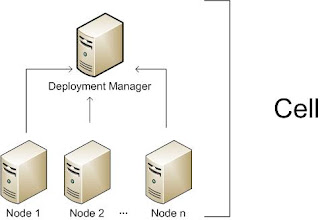
 Figure 1
Servers
WebSphere Application Server supplies application servers which provide the functions that are required to host applications. It also provides the ability to define external servers to the administration process.
In the next post (PART 2) of this series I will describe the installation process and strategy of MyApp on WAS.
In this post I will try put together a brief on WAS concepts and overview required to go ahead with the deployment plan.
WebSphere Application Server: An overview
WAS is the implementation by IBM of the Java 2 Enterprise Edition (J2EE) platform. It conforms to the J2EE 1.4 specification.
WebSphere Application Server is available in three unique packages that are designed to meet a wide range of customer requirements.
_ IBM WebSphere Application Server - Express V6
_ IBM WebSphere Application Server V6 - Base
_ IBM WebSphere Application Server Network Deployment V6
Network deployment platform
We used Network deployment (ND) version for the installation described below.
With ND, a distributed server configuration can be set up, which enables
# central administration,
# workload management and
# failover.
In this environment, one or more application servers are integrated into a cell that is managed by a deployment manager. The application servers can reside on the same machine as the deployment manager or on multiple separate machines. Administration and management is handled centrally from the administration interfaces via the deployment manager. With this configuration, multiple application servers can be created to run unique sets of applications and then manage those applications from a central location. However, more importantly, one can cluster application servers to allow for workload management and failover capabilities. Applications that are installed in the cluster are replicated across the application servers. When one server fails, another server in the cluster continues processing. Workload is distributed among Web containers and Enterprise JavaBeans containers in a cluster using a weighted round-robin scheme. Figure 1 illustrates the basic components of an application server in a distributed server environment.
Application servers, nodes, and cells
Regardless of the configuration, the WebSphere Application Server is organized based on the concept of cells, nodes, and servers. While all of these elements are present in each configuration, cells and nodes do not play an important role until you take advantage of the features provided with Network Deployment.
Application servers
The application server is the primary runtime component in all configurations and is where an application actually executes. All WebSphere Application Server configurations can have one or more application servers. In the Express and Base configurations, each application server works as a separate entity. There is no workload distribution or common administration among application servers. With Network Deployment, a distributed server environment can be built consisting of multiple application servers maintained from a central administration point. In a distributed server environment, one can cluster application servers for workload distribution.
Nodes, node groups, and node agents
A node is a logical grouping of server processes that are managed by WebSphere and that share common configuration and operational control. A node is associated with one physical installation of WebSphere Application Server. In a stand-alone application server configuration, there is only one node. With Network Deployment, multiple nodes can be configured that can be managed from one common administration server. In these centralized management configurations, each node has a node agent that works with a deployment manager to manage administration processes.
A node group is a new concept introduced with WebSphere Application Server V6. A node group is a grouping of nodes within a cell that have similar capabilities. A node group validates that the node is capable of performing certain functions before allowing those functions. For example, a cluster cannot contain both z/OS nodes and nodes that are not z/OS. In this case, multiple node groups (one for the z/OS nodes and one for nodes other than z/OS) can be defined. A DefaultNodeGroup is automatically created based on the deployment manager platform. This node group contains the deployment manager and any new nodes with the same platform type.

Cells
A cell is a grouping of nodes into a single administrative domain. In the Base and Express configurations, a cell contains one node. That node may have multiple servers, but the configuration files for each server are stored and maintained individually.In a distributed server configuration, a cell can consist of multiple nodes which are all administered from a single point. The configuration and application files for all nodes in the cell are centralized into a cell master configuration repository.
A cell is a grouping of nodes into a single administrative domain. In the Base and Express configurations, a cell contains one node. That node may have multiple servers, but the configuration files for each server are stored and maintained individually.In a distributed server configuration, a cell can consist of multiple nodes which are all administered from a single point. The configuration and application files for all nodes in the cell are centralized into a cell master configuration repository.
 Figure 1
 Servers
WebSphere Application Server supplies application servers which provide the functions that are required to host applications. It also provides the ability to define external servers to the administration process.
In the next post (PART 2) of this series I will describe the installation process and strategy of MyApp on WAS.
Wednesday, March 24, 2010
Killer Servlet: a performance tuning and garbage collection solution
An applet is a Java application executed by a web browser to show dynamic graphics on the front-end. After the advent of Rich Internet Application (RIA) technologies, applets are disappearing from the tech landscape but once upon a time it was the only way to show rich contents on the front-end. A servlet in brief is a piece of Java code executed on the server side (typically a web server with an embedded servlet engine) to process request, collect data from data source or rendering a well formatted HTML page on the browser.
An applet-servlet communication is typically done where one can not avoid having a thick client such as an applet on the front-end posting requesting and / or receiving feed from the server side. For example, suppose an applet is continuously drawing and updating a graph based on the feeds received from the servers on the stock prices.
Whenever a user is opening an applet on his/her browser, the browser is downloading the applet and starts executing it. The applet draws a nice graph on the front-end (browser) and on the background connects to a server to fetch stock prices. When we had such a situation back in 2001/2002 (original situation has been modified a little to keep the privacy of the project intact) the architecture followed to implement this is as follows.
Among the technical components there were
• A Stock Price Applet with
o a nice graph panel
o a thread to render the graph on the front-end
o a thread to communicate with a servlet at the back-end
• A Stock Price Servlet (HTTPServlet) on the server with a “while” loop in the doPost() method and having some sub-components as below.
o a JMS Listener attached to the Stock price JMS topic
o a shared message cache where the subscriber stored the messages and the servlet used to read from.
• A Stock price JMS Topic on the JMS server
• Multiple Stock price publishers connected with different external Stock servers on the outer end and with the Stock price JMS topis on the inner end (in the server). Figure 1 explains the architecture.
 Figure 1
The applet used to run on the browser and communicate (by opening a http stream) with the StockPriceServlet at the back-end. The servlet used to instantiate the JMS subscriber on receiving the applet’s request. The JMS subscriber was connected with the Stock price JMS topic to listen to Stock price update messages. On the other hand the JMS publishers kept adding messages as and when received from the external servers. To keep the http session alive between the applet and the servlet an infinite “while” loop is placed in the doPost() method of the servlet. The communication was a server push within an http session continuation.
Everything was nice and smooth but after serving a certain number of clients (i.e. applets) the server was getting slower and slower. It was a real-time application and delays to a certain extent was permissible but not beyond that.
So we started investigating the reason behind it. We discovered that the StockPriceServlets those were serving the applets on the front-end were kept alive even after the applet window was closed. The reason was the infinite loop in the doPost() method. The JMS subscriber was still alive listening to the JMS topic and throwing the messages to the servlet. The StockPriceServlet was writing the messages on the http response stream without any errors/exceptions because it was unable to sense that the receiver on the other side of the stream (i.e. the applet) has been stopped.
There was an option to put a timeout on the servlet so after a certain period pf time it dies out but that was not optimal. With an increased frequency of updates received by the stock servers the system might choke anytime.
Another option was to send a completion request from the applet to the servlet so that it can come out of the loop. But once the servlet receives the first request from the applet it starts the JMS subscriber and goes inside the loop. Http communications are stateless therefore a new request will invoke a new servlet.
Looking for more options we figured out a way to stop the StockPriceServlet and free up the resources with a programmatic technique. It was quite clear that the servlet needed to be killed on the completion of the applet’s activities. So an event or update needs to be thrown back to the servlet notifying that the applet has been stopped. Based on this update the servlet had to be killed. So we felt the need of an agent on the server side who will receive the notification from the applet’s end. The agent needs to accomplish the following activities.
1. Receives the completion notification from the applet.
2. Identifies the StockPriceServlet instance that was serving the applet.
3. Notify the servlet by updating a flag that makes the servlet to break out from the infinite loop and stop the subscriber attached to it.
So the agent took birth as the KillerServlet (please don’t laugh :) it’s the birth of the terminator ;). Activity 1 can be easily achieved by sending a http request from the applet to the KillerServlet. The most critical was the step 2 i.e. to identify the servlet instance. All servlet instances were maintained by the servlet container and hence getting a hold with them is tough. Well, getting the reference of a servlet from the ServletContext method was easy and official during 2001/2002 , but the issue was to identify the exact subject for kill i.e. a correlation. To establish a correlation the participants in the communication channel i.e. the applet and the servlet should be marked / tagged with a unique id (a correlation id) that can be used later to get a reference of the participants.
Figure 2 explains the modified architecture to include the solution. The solution technique was conceptualized as below.

Figure 2
1. The applet connects with the StockPriceServlet.
2. The StockPriceServlet generates a unique id (correlation id) and sends back the same to the applet with the first response before entering the loop. The StockPriceServlet should have a flag to terminate the while loop e.g. “while(!completed){}” instead of “while(true){}”. The StockPriceServlet should also have a unique id generator (preferably a singleton object).
3. The StockPriceServlet sets an attribute to the ServletContext (ServletContext.setAttribute()) with its own reference against the unique id.
4. Once the applet receives the unique id it should store the same.
5. Once the applet is stopped or terminated it should be able to sense the same (may be by using a JavaScript or a close button) and invoke the KillerServlet with the unique id.
6. The KillerServlet receives the unique id and looks up for the same in the ServletContext. (ServletContext.getAttribute()).
7. On receiving the appropriate reference to the StockPriceServlet instance the KillerServlet should update the completion flag to “true” in the StockPriceServlet instance.
8. Once the while loop is terminated, the StockPriceServlet stops the JMS subscriber and cleans up the message cache.
We did not want to invoke the destroy method to avoid touching the lifecycle controls and left the rest of things on the servlet container.
Monday, March 8, 2010
TOGAF and SOA
I am with a mission to define the technology architecture i.e. the phase D in TOGAF ADM (http://www.opengroup.org/architecture/togaf8-doc/arch/chap03.html). Days are changing, the current trend (try with google) is SOA :)
So everything should be done in SOA way. TOGAF is an architecture framework while SOA is an architectural style. TOGAF does not mention any specific architectural style to be followed, so I can use SOA with out any issue. Technology architecture as defined by TOGAF needs input from the business and application architecture as well.
During the last couple of years people used object oriented paradigm more conveniently with most of the IT system architecture, analysis, design and development. SOA can be used as an architectural style during the analysis (not sure if the business can always be analised in terms of services) design and modeling but once it comes to the implementation arena it's no more SOA. Services are implemented as web services or something else similar to that. Finally it boils down to files, dlls, java classes, exe, xml file etc. It's hard to distinguish the bricks collapsed out of a charch or a library or a skyscraper after an earthquake :)
When there's no abstraction, there's no SOA or object orientation or any other style, they are all the same. Finally all the services and objects are going to be converted to the binary language for the machine to execute.
To me the technology architecture that talks about the concrete deployment environment for a system or application has got very less to do with SOA.
Digging the lower level details of the BPEL process engines or ESBs will return the application server underlying. ESB and BPEL process engines are mostly deployed as applications on the top of an application server for most of the vendors (be it Webspehere or Weblogic).
Wednesday, February 24, 2010
Multimedia search engine
One more abstract useless thought.
Till date the search engines that we use on the internet are also text-based search engines. These search engines will typically have a box to put your text followed by a neat button to click on to begin with the search. On submission of your search request you will get a well formatted page containing all the search results. Usually a bunch of links following different websites are presented. In case it's an image or video search links to the image/video resources are listed.
Computers are intended to become close to human brain with the ability to interact using all the sense organs like human beings. Will you recognize my face from a group photo taken while I was in school? tough :) If you can I must say you have a good eye-sight and power of pattern recognition, that's human brain. I hope someday we will have search engines to upload the image of my face and find out a group photo posted somewhere on the net. Exciting, aint it!! we can do this with many media patterns such as
# image
# video
# sound/music
I could have added more to the list if we had smell, taste and touch :) but we don't have input/output devices for them yet. ooops!! sorry it's not my concept (well every computer user might have thought this way while seeing a lovely photo of a food S/he likes) but has been patented recently (http://www.patentstorm.us/patents/7562816/description.html). I would hope we will see it commercially available in the market soon. Even there are touch printers in the market too (http://www.gizmag.com/sense-taste-smell-touch-printer/13689/).
Image pattern recognition will help greatly in finding out photos from the internet for the purpose of research, investigation.
Sound patterns would track down the copied or pirated music ;) and videos will help in tracking down piracy.
Friday, February 12, 2010
I don't see my words in your design
It has always been a long and tough session to make the business people understand the thought process behind attaining a particular design model. In my career as a software designer I faced several categories of stakeholders for my design such as the IT-managers from the client's side, technical IT people, business people, end-users etc.
Usually we go and meet these users to grab the requirement of the system/application they are looking for and then try to draw a mapping between the requirement and the software logical constructs such as classes, objects, services, components etc. During the process some new terms pop up based on the abstraction of the designer which might not surface the exact word specified in the requirement. Designers try to map the features/requirement of the application with the logical software constructs which is sometimes beyond the understanding of some of the stakeholders.
Based on the technical knowledge on software design of the stakeholder it becomes harder or easier to bridge the gap and make them happy. I am sure all the designers have experienced these kinds of sessions where the audience is shouting at you syaing "I don't see my words in your design, make me understand how are you arriving at this model of yours..". It will be followed by a long discussion of why I did it.
For example, a person who drives a car might not be very familier with the internal structure or mechanism of a chasis or gear box, but you have to make him/her understand how is it related to the process of driving else S/he will not buy the car... I just had this kind of session today :)
Subscribe to:
Posts (Atom)
-
 These days Enterprises are going ahead with their plans for clustering as a mandatory factor in their mission-critical applications. There a...
 -
 There are multiple issues faced by conventional IT companies on the way to implement effective SOA governance. Lack of decision on what serv...
 -
 Whether an IT project is of development, integration or transformation type, Technology Selection has always been a critical activit...